



14 Jul Architectural fountain design and equipment
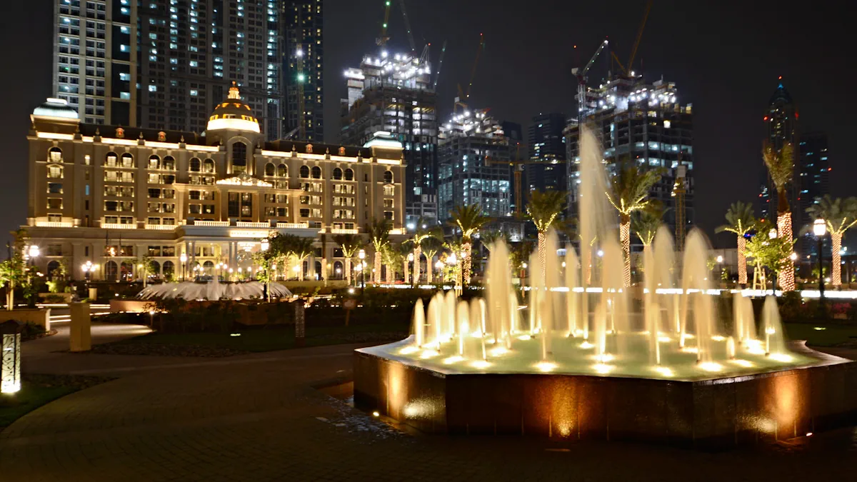
An architectural fountain should not be understood as a mere collection of independent components, but rather as an integrated technical system. The visible outcome —jets, lighting, movement, water stability, or operational ease— depends on hydraulics, treatment, electricity, lighting, and control working in a coordinated manner from the project's inception.
This approach is particularly crucial for architectural fountains in public and urban spaces, hotels, shopping centers, or architectural projects where the system must operate regularly, adapt to its environment, and be maintained in optimal condition for years. Not all installations demand the same technological level: a static composition can be managed with simple logic, whereas dancing fountains, dry deck fountains, or interactive fountains require more advanced control layers.
The key lies in correctly defining the installation's typology and, subsequently, dimensioning each component with a holistic perspective.
An architectural fountain as a system, not a catalog of components
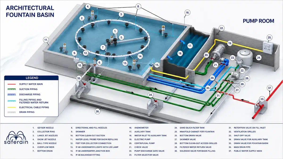
The technical value of an architectural fountain lies architectural only in The fountain head nor on the height of the water jets. A fountain head works properly if it receives the proper flow rate, if the manifold distributes the water evenly, if the pump is properly selected, if the water level remains stable, and if the control system It coordinates schedules, sensors, lighting, and operating modes.
Therefore, the design must begin with a systemic approach. Each component of the architectural fountain performs a specific function, but also interacts with other elements. When this relationship is overlooked, problems such as splashing, jet misalignment, maintenance difficulties, unnecessary consumption, or loss of visual quality arise.
Holistic view of an architectural fountain system
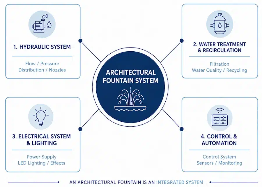
An architectural installation is organized around four major technical subsystems.
-
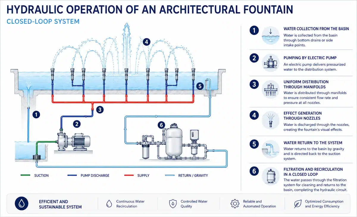
- Hydraulic System: This is the physical foundation for the operation of an architectural water fountain. It draws water from the basin or auxiliary tank, propels it using electric pumps, distributes it through piping and manifolds, and delivers it to the fountain heads with the required flow rate and pressure. It determines the uniformity of the water jets, visual stability, energy consumption, and wind response.
- Treatment and Recirculation System: Its function is to maintain the water in perfect condition both chemically (pH, Chlorine, etc.) and by removing suspended solids, while sustaining a stable operational regime. It includes a main drain, skimmer, directional fountain heads, filtration pump, sand filter, automatic filling, auxiliary tank, chemical treatments, and drainage lines. The design principle is to operate in a closed circuit, replenishing only losses due to evaporation or splashing.
- Electrical and Lighting System: This system powers underwater lights, sensors, actuators, and the control panel. Lighting should not be an afterthought but rather defined in conjunction with the hydraulics so that color, optics, power, and control are aligned with the water effect.
- Control and Automation System: This is the layer that coordinates the actual behavior of the entire system: schedules, sensors, sequences, automatic replenishment, lighting, and height variation. In simple installations, basic logic may suffice; however, in dancing fountains or dry deck fountains with dynamic and interactive systems, control becomes a critical infrastructure.
Architectural fountain design and equipment
Below, we group the components of the architectural fountain by categories to aid in understanding the installation and facilitate its comprehension. The technical classification can be read as follows:
- Water emission and architectural structure.
- Basin, water intake, level, and replenishment.
- Pumping and delivery system.
- Filtration, suction, and return.
- Lighting, waterproofing, and control.
- Supply, ventilation, and drainage.
This classification does not replace individual analysis. Each component must be understood separately to ensure the design is coherent, maintainable, and easy to operate.
Water emission and architectural structure
The emission elements are responsible for transforming the hydraulic flow into a visual effect. In an architectural fountain, these components do not operate in isolation: they depend on the water pump, manifold balance, circuit regulation, and basin geometry. Their correct selection and adjustment are decisive for architectural fountains to maintain uniformity, stability, and visual quality during operation.
Following the numbering in the main image, which displays all components of an architectural fountain, we present those involved in water emission:
- No. 1 – Geyser Fountain Head: The geyser fountain head, categorized among foamy water jets, mixes water propelled by the main electric pump with water from the basin and air, generating a white, foamy-looking jet. In an architectural fountain, it is typically used as a prominent visual element and must be connected to a stable supply network, coordinated with the main pump and circuit regulation. This fountain head is dependent on the water level in the basin, making its monitoring crucial. To maintain the quality of the water effect, it is advisable to provide access for cleaning and readjustment, as well as to integrate its operation with schedules, an anemometer, or pump modulation when it is necessary to reduce splashing or adjust the jet height.
- No. 2 – Collector Ring: The collector ring distributes the propelled water to the lance jet fountain heads installed on it. It is a fundamental element in circular or geometric compositions, as the homogeneous flow of all jets depends on its balance. In architectural fountains, it must be supported by mounting feet, correctly connected to the supply network, and allow for adjustments during commissioning to control pressure losses, leveling, and mechanical stability.
- No. 3 – Lance Jet Fountain Heads: Lance jet fountain heads produce crystalline and defined jets, suitable for clean and geometric compositions. Their performance depends on the collector's balance, the hydraulic quality of the circuit, and wind conditions. In an architectural fountain, they require well-filtered water, stable flow, and the possibility of periodic alignment using Ball Joints, especially when a precise visual interpretation of the ensemble is desired.
- No. 4 – Snow Jet Type Fountain Head: The snow jet type fountain head mixes propelled water and air to produce a white, foamy, and voluminous jet. It adds body and visual presence to the composition, acting as a counterpoint to more defined jets. In the design of architectural fountains, its sound level, wind response, and potential splashing must be evaluated, always in relation to the available pressure and the overall balance of the circuit.
- No. 5 – Ball Joint Type Ball: This allows adjustment of the verticality or inclination of the jet generated by the associated fountain head. Although a small component, it directly influences the final quality of the effect, as it enables correction of misalignments during commissioning or maintenance. In an architectural fountain, it must remain accessible and maintain a stable position to prevent displacement due to vibration, manipulation, or continuous operation.
Basin, intake, level, and replenishment
This group gathers the components that allow the basin to be maintained in operational conditions: they control the level, facilitate water intake, aid in cleaning, and ensure replenishment when losses occur due to evaporation or splashing. In urban architectural fountains, their correct integration is key for the system to operate in a closed circuit and remain maintainable over time.
- No. 6 – Overflow: This component evacuates water exceeding the desired basin level, preventing overflows in situations such as rainfall or unexpected water input. In an architectural fountain, it operates in conjunction with the drainage network, thus requiring sizing as part of the hydraulic balance. Its design must facilitate cleaning and ensure evacuation capable of absorbing peak flows without backflow or pooling.
- No. 7 – Bottom Drain: This allows the basin to be emptied and is a key point for the general maintenance of an architectural fountain, as it is involved in the draining process. It must be coordinated with the basin's slopes, the bottom drain valve, and the general drainage system to prevent dead spots and facilitate complete water evacuation.
- No. 8 – Directional and Filling Fountain Heads: Directional and filling fountain heads supply water to the basin and, when correctly oriented, propel surface debris towards the skimmer. In architectural fountains, their function combines replenishment and enhancement of surface circulation, thus they should not be considered merely as filling points. Their orientation must be verified during operation to ensure they continue guiding the water sheet towards the surface intake.
- No. 9 – Skimmer: The skimmer collects floating debris from the basin's surface and directs it towards the filtration circuit. In an urban fountain or any architectural fountain exposed to the environment, its placement facing the prevailing winds improves surface collection. It must work in coordination with the directional fountain heads, the skimmer valve, and the filtration pump, keeping the basket and lid accessible for periodic cleaning.
- No. 10 – Suction Fountain Head for the Bottom Cleaner: The suction fountain head for the bottom cleaner allows connecting a self-floating hose and a vacuum head to aspirate dirt deposited at the bottom of the basin. In an architectural fountain, it is a service point directly associated with cleaning and should be located where operator maneuverability is practical. Its effectiveness depends on a clear connection with the suction circuit, the bottom cleaner valve, and the filtration pump.
- No. 11 – Level Sensor for Architectural Fountain Refill: The level sensor detects when the water level drops below the preset value and activates the filling solenoid valve. In architectural fountains, this component automates replenishment and helps maintain a stable working volume, especially when an auxiliary tank is present. It must be located in an area representative of the effective level and be accessible for checks, integrating with reliable filling logic.
- No. 12 – Collector Mounting Feet: These secure the collector to the basin floor and provide it with appropriate height and level. In an architectural fountain, their structural function directly impacts the geometry of the jets, as any collector misalignment results in a loss of visual quality. They must allow for precise leveling and adequately withstand the submerged environment.
- No. 17 – Auxiliary Tank: The auxiliary tank is an optional volume that helps maintain the water level during operation and ensures the minimum required depth for the main pump. In architectural fountains that require greater hydraulic stability, it allows buffering level variations and reusing system water. It must be integrated with the inlet from the basin, the filling solenoid valve, the level probe, and the auxiliary drain, providing sufficient access, its own drainage, and ventilation when part of the technical room.
- No. 18 – Architectural Fountain Water Inlet to the Auxiliary Tank: This water inlet conveys water from the basin to the auxiliary tank, connecting both working volumes. In an architectural fountain, its mission is to contribute to maintaining the desired level and promote system stability. It must be sized to prevent constrictions and erratic level readings, integrating correctly with automatic filling, emptying of the auxiliary tank, and the actual capacity of the compensation volume.

Pumping and propulsion system in the architectural fountain
The pumping and delivery system provides the necessary hydraulic energy for an architectural fountain to generate its water effects. Pumps and valves determine the flow rate, pressure, regulation capability, and ease of maintenance. In architectural water fountains, this group must always be sized in relation to the fountain heads, manifolds, and the dynamic load of the circuit.
- No. 19 – Electric Pump for Nozzle or Fountain Head Operation: The main electric pump propels water towards the nozzles or architectural fountain heads. The flow rate, pressure, and actual quality of the water effect depend on it. In an architectural fountain, it can be located in a technical room or as a group associated with the main hydraulic system, working with suction and discharge valves, collectors, fountain heads, and the control panel. Its selection must be based on the total flow rate and the required dynamic head; when justified by the project, frequency converters provide modulation, efficiency, and smooth starting.
- No. 20 – Gate Valve: This gate valve regulates the flow rate in the main pump's suction line and allows the pump unit to be isolated for removal without emptying the basin. In an architectural fountain, its accessibility and identification are essential as it facilitates maintenance, replacement, or intervention on the pumping unit. It must be integrated into the suction line with clear and secure operation.
- No. 21 – Gate Valve: The second gate valve regulates the flow rate or pressure of water supplied to fountain heads and collectors. In architectural fountains, it is crucial during commissioning, as it allows for adjustment of the water effect and balancing of the circuit. The design includes placing a check valve downstream to prevent water hammer towards the electric pump, thereby enhancing the hydraulic stability of the system.
Filtration, suction, and return
Filtration maintains water in optimal conditions through intake, mechanical treatment, and return to the basin. In an architectural fountain, this subsystem not only enhances water quality but also facilitates daily operation and reduces incidents related to surface debris, sediments, or undesired backflows.
- No. 22 – Electropump for the Purification System: The purification electropump propels water towards the sand filter and returns the filtered water to the basin via the directional fountain heads. In architectural fountains, it operates with a bottom drain, skimmer, bottom cleaner connection, selector valve, and filtered return. Its sizing must be consistent with the system volume and associated filter, and its location should promote accessibility, ventilation, and ease of isolation.
- No. 23 – Purifier Selector Valve: The selector valve allows choosing between filtration, backwash, rinse, recirculation, closed, and drain modes. In an architectural fountain, it makes the sand filter operable and maintainable, thus requiring an accessible position and ease of interpretation for operating personnel. Effective purification depends on both the filter and the actual ease of backwashing and resetting the system without operational errors.
- No. 24 – Silica Sand Filter Tank: The silica sand filter tank retains impurities present in the water and returns clean water to the basin. It is the core of basic mechanical treatment in many architectural fountains. Its effectiveness depends on the recirculation flow rate, proper backwash operation, and general system cleanliness; therefore, it must be designed with convenient access to reduce downtime and facilitate stable operation.
- No. 26 – Bottom Drain Valve: This valve allows emptying the architectural fountain to perform maintenance tasks that would otherwise be impossible. Its position and operation are crucial to avoid errors in completely emptying the basin, which would result in significant water waste. Its position and operation must be clear to simplify cleaning, filtration, and commissioning.
- No. 27 – Skimmer Valve: The skimmer valve allows water to be drawn from the skimmer towards the purification system, regulating surface intake. In architectural fountains, its adjustment helps improve surface skimming and can vary depending on surface debris or maintenance strategy. It must be easy to identify and operate.
- No. 28 – Bottom Cleaner Valve: The bottom cleaner valve allows suctioning, via a vacuum head, the debris deposited at the bottom of the basin and sending it to the purifier. In an architectural fountain, it is a service component for spot cleaning and must be accessible during operation. The more organized the valve and intake layout, the simpler daily operation will be.
- No. 29 – Check Valve for Filtered Water Return Line: This check valve prevents filtered water from returning to the silica sand filter tank. In an architectural fountain, it maintains the correct flow direction between the filter and the return to the basin, preventing undesired backflows when the system stops. It must be located accessibly and consistently with the overall circuit operation.
Lighting, watertightness, and control of the architectural fountain
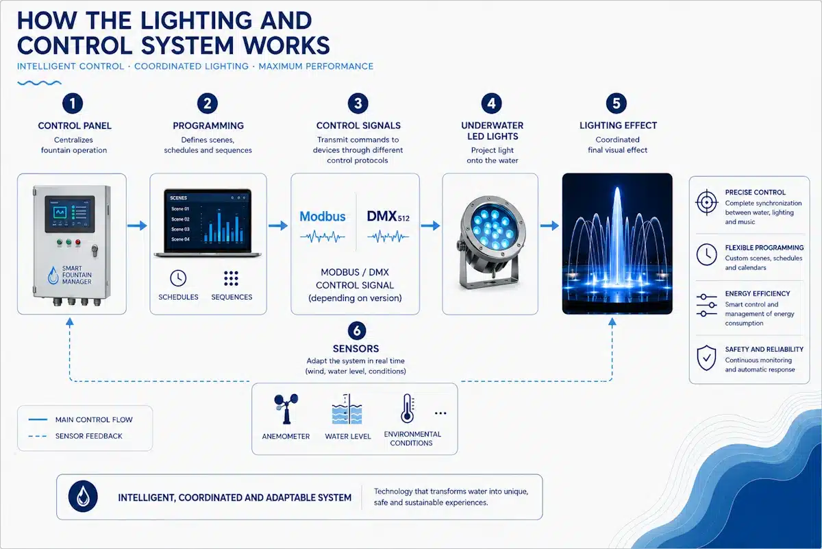
Lighting, watertight connections, and control devices extend the functionality of an architectural fountain, enabling the coordination of water, light, sensors, and automation systems. In dancing fountains, dry deck fountains, or interactive fountains, this layer gains particular importance as it determines both the visual experience, operational safety, and ease of maintenance.
- No. 13 – IP-68 Submersible Spotlights with LED Lamp: IP-68 submersible spotlights with LED lamps illuminate the architectural fountain from within the basin and can generate various colors via DMX control. In an architectural fountain, they must be coordinated with the water effects, sheets, or perimeters intended for enhancement, working with junction boxes, cable glands, and the control panel. It is advisable to define their number, power, optics, and control logic from the project's inception, integrating lighting with hydraulics to ensure the nocturnal effect is not a late addition.
- No. 14 – IP-68 Submersible Junction Box: These allow for electrical connections for spotlights, solenoid valves, and other submerged elements, maintaining complete watertightness. In architectural fountains, it acts as a link between submerged equipment, cable glands, and wiring to the control panel. Its design should prioritize order, reasonable accessibility, and consistency with the electrical layout to reduce incidents and facilitate future interventions.
- No. 15 – IP-68 Cable Gland: This allows cables to pass from the exterior to the interior of the basin without water penetration. In an architectural fountain, it fulfills a sealing and transition function between civil works and the electrical or control installation. It must be addressed from the executive project stage, coordinated with walls, submersible junction boxes, and the control panel, avoiding improvised solutions during construction.
- No. 16 – Anemometer: This controls the operation of the architectural fountain according to wind speed and can reduce or cancel the height of the jets to prevent external splashing. In architectural fountains with tall jets, sprays, or waterfalls, this sensor helps conserve water, enhance environmental comfort, and extend operational uptime. It must be installed at a point representative of the wind affecting the jets and connected to the control panel's logic.
- No. 25 – Control Panel for Architectural Fountain, Submersible Lights, and Purification: The control panel programs the hydraulic and lighting operation of the fountain and allows for varying jet heights through variable speed drives. In an architectural fountain, it centralizes pumps, lighting, sensors, automation systems, and purification, interfacing with an anemometer, level sensor, lights, solenoid valves, and pumping systems. It must be selected according to the actual project complexity, ranging from basic panels to advanced platforms with DMX, remote control, and scene programming.
- No. 30 – Solenoid Valve for Filling the Architectural Fountain and Auxiliary Tank: The filling solenoid valve enables automatic filling and refilling of the basin and auxiliary tank, operating in conjunction with the level sensor. In architectural fountains, it is the primary actuator of the replenishment system and is positioned between the supply network and the basin or auxiliary tank. It must be integrated with stable level logic, the inlet check valve, and the supply valve to prevent backflows or erratic openings.
Supply, ventilation, and drainage
These components connect the installation to the external supply, ensure water evacuation, and protect the technical room. Although often perceived as auxiliary elements, in an architectural fountain, they are crucial for hydraulic safety, maintainability, and long-term operation.
- No. 31 – Check Valve at the Filling Inlet: The check valve at the filling inlet prevents water from the fountain from returning to the supply network. In an architectural fountain, it maintains the correct direction of the supply flow and operates with the supply valve, the filling solenoid valve, and the public network. It must be accessible for inspection and form part of a clear and maintainable filling line.
- No. 32 – Ventilation Grilles: Ventilation grilles allow for natural ventilation of the pump room and prevent condensation inside. In architectural fountains, a well-ventilated technical room improves working conditions, reduces ambient humidity, and promotes the durability of pumps, control panels, and other equipment housed within. They should not be treated as a secondary aspect of the project.
- No. 33 – Supply Valve: The supply valve connects the installation to the public network and allows for manual control of water input to the system. In an architectural fountain, it operates in conjunction with the filling solenoid valve and the inlet check valve. It must be clearly identified and accessible, as it is involved in startup, emptying, controlled replenishments, and maintenance operations.
- No. 34 – Auxiliary Tank Drain Valve: The auxiliary tank drain valve allows for emptying this compensation volume for cleaning or intervention. In architectural fountains with an auxiliary tank, it facilitates inspections, cleaning, and extended shutdowns. Its operation must be straightforward, and the drainage path must be properly designed.
- No. 35 – Architectural Fountain Drain Valve: This drain valve allows the basin to be emptied via the bottom drain. In an architectural fountain, it is part of the maintenance sequence and must be coordinated with slopes, the bottom drain, and the main drainage system. The clearer the emptying operation, the simpler the installation's operation will be.
- No. 36 – Main Drainage Pipe: The main drainage pipe collects and conveys system drainage outside the installation. In architectural fountains, it can receive contributions from the basin, overflow, or auxiliary tank, depending on the designed configuration. It must be sized with sufficient margin and a logical layout to prevent backflows, obstructions, or drainage issues.
- No. 37 – Public Supply Network: The public supply network is the external water source for system filling and replenishment. In an architectural fountain, it connects to the filling line via the supply valve, check valve, and solenoid valve. Effective management of water level, wind conditions, and the closed circuit allows for reducing its use to only strictly necessary replenishment.
Current Design Criteria
-
- Correct Hydraulic Sizing: The pump, valves, manifold, and fountain heads must be defined as a cohesive unit. The total flow rate, dynamic head, head losses, and regulation collectively determine the quality of the effect.
- Appropriate Level of Automation: Control systems must manage schedules, sensors, lighting, and safety without introducing unnecessary complexity. In interactive fountains, dry deck fountains, or dynamic installations, this layer requires special attention from the project phase.
- Maintenance-Oriented Design: Maintainability is determined by specific details: accessibility of pumps and valves, skimmer cleaning, connection access, technical room ventilation, clear drainage paths, and ease of adjusting fountain heads.
Automation and Control: The Appropriate Technological Level
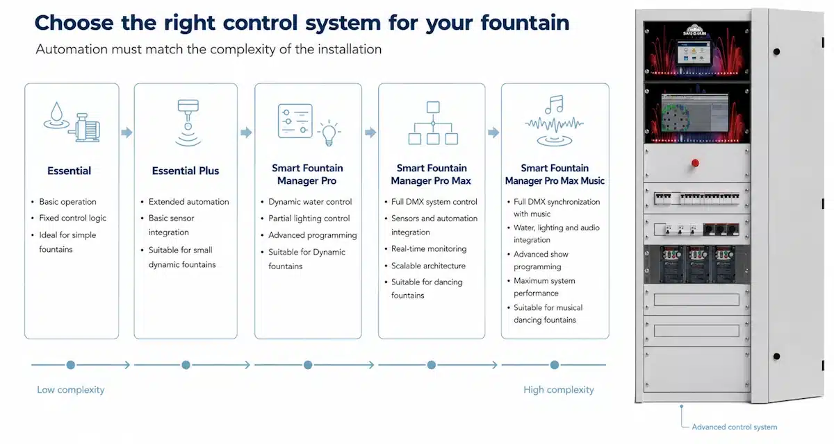
The control system it does not replace hydraulics or lighting; it coordinates them. In modern installations, it defines when the system operates, how it responds to wind, how water is replenished, how lighting is programmed, and what degree of dynamism it can achieve.
The control technology utilized in the architectural fountain must align with its typology. A static composition requires basic pump control and protection, scheduling, and simple lighting, which can be managed with Essential technology. A basic dynamic composition may necessitate additional water pumps, pre-configured programs, level control, and an anemometer, solvable with Essential Plus or Smart Fountain Manager Pro technologies. Advanced installations, such as SFM Pro Max and Pro Max Music, integrate multiple hydraulic circuits, variable frequency drives, DMX, custom programming, remote control, and, for dancing or musical fountains, synchronization between water, light, and music.
The crucial decision is not to add complexity, but to select the appropriate level of complexity. An overly basic system restricts operational potential; an excessively sophisticated one can complicate maintenance and operation if it does not align with the actual typology.
Common errors in the design of architectural fountains
The primary error is to design an architectural fountain without a systemic vision. Selecting fountain heads or lighting without reviewing manifolds, pumping, water level, and control typically leads to operational issues.
The second common issue is integrating the fountain control system too late. If sensors, control panels, variable frequency drives, and lighting are not coordinated from the outset, the installation loses flexibility and becomes more challenging to operate.
The third relates to hydraulic or maintenance decisions: poorly accessible valves, inadequately designed drainage, inefficient surface distribution, or insufficiently integrated filtration. These are discrete aspects, yet they determine the operational lifespan of the entire system.
Conclusion
The success of architectural fountains depends on the balance among all their components. The visual quality of the water is the visible aspect of a broader engineering discipline, encompassing hydraulics, treatment, lighting, sensors, automation, drainage, and maintenance.
When each element is selected and positioned with the complete system in mind, the installation performs more efficiently, consumes resources more judiciously, requires less maintenance, and can adapt to various operational modes. This distinguishes a mere assembly of parts from a coherent technical solution for urban, public, and architectural projects.
No Comments